
How to change keyboard layout using visual online editors VIA and REMAP


VIA and REMAP are great online visual tools to re-define QMK-based keyboards. All current ThumbsUp! keyboard support both tools by default.


Configuration File

Download JSON file for your board from here: https://www.dropbox.com/scl/fo/2s8vz5tq5lffmpjuqbz2c/h?rlkey=71amow1mhhwfe54c0ywx59bfc&dl=0


v2 Atmega: rev2_atmega_via.json

v2 RP2040: rev2_rp2040_via.json

v3, v4: rev3_rp2040_via.json

v5, v8: rev5_promicro_unibody_5x12_via.json

v6: rev6_rp2040_5x6_via.json

v7: rev7_rp2040_5x6_via.json


How to use VIA


In web-browser navigate to https://usevia.app/:


Click on Settings icon:


Click on "Show Design Tab" toggle, so it is moved to the right:


"Design" icon should be visible on top of the screen:


Click on it, this screen should appear:


Move "Use v2 definition" toggle to OFF (left) position.

Click on the "Load" button and select the JSON file downloaded before.
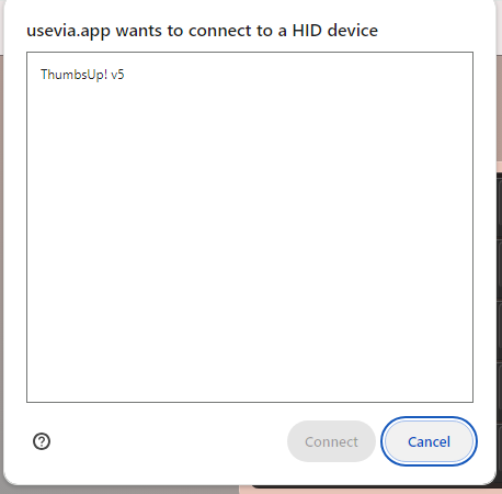
 

A pop-up window may appear, select your keyboard and click Connect:


Click on Configure icon:


Modify your keys, they changes should become effective immediately:


How to use REMAP

In your browser navigate to https://remap-keys.app/configure.


Let the site to modify your keyboard, click on "+KEYBOARD" and connect your board:


If the site asks for the keyboard definition file, click on "IMPORT (.JSON)" and specify the configuration file downloaded earlier:


Modify the layout:


Once the layout is ready - flash it by clicking on "Flash" button in the top right corner:


Please note these steps are a temporary solution. Once I register my boards with VIA and REMAP there will be no need to upload JSON file.


Comments

Popular posts from this blog

Adding a Touchpad

  Updated:   Jun 5 The unibody ThumbsUp! keyboards support ProGlide Cirque touchpads. Cirque touchpad fits nicely under the top PCB and are not visible from outside, so here its picture sticking out, not yet glued to the top PCB:     There are tracks leading to a connector on the top board. (Add it to the order and let me know if you want the connector to be installed, provided I have them in stock.)     You'd need to buy these two parts from Mouser (or any other vendor): Mouser #: Mfr. #: Desc.: 355-TM0400402024-301 TM040040-2024-301 Capacitance Touch Sensor Modules Capacitance Touch Sensor Modules 40mm Round SPI/I2C adhesive overlay 538-15166-0125 15166-0125 FFC / FPC Jumper Cables FFC / FPC Jumper Cables FFC 0.50 Type A 12 ckts lgt 127   Touchpads need to be modified: R1 needs to be removed to use I2C the boards support:   For the ProMicro and Atmel32U4-based keyboards the touchpad also needs to be made t...

Source Files and Default Firmware

Updated:   Nov 12 I am cleaning up the firmware for all the keyboards. Two biggest changes are switch to the current QMK version 0.22.14 and enabling the VIA/REMAP support for all the keyboards. Look for the banners for each keyboard to see if the new firmware is ready.   Default (pre-compiled) firmware and JSON files for VIA/REMAP are in Dropbox here:   https://www.dropbox.com/scl/fo/2s8vz5tq5lffmpjuqbz2c/h?rlkey=71amow1mhhwfe54c0ywx59bfc&dl=0   You can flash them to your board. For AtMega/ProMicro based boards (*.hex files) use  QMK Toolbox  . For RP2040 boards (*.uf2 files) press twice the reset button (on the bottom side of the middle PCB), and copy the file to the drive newly added to the system. Note: v3 (5x12) and v4 use the same firmware (use the v4 one as the latest and supporting VIA/REMAP.) //TODO: re-upload v4   v5, v8 and v8b also use the same firmware (use v5 for all of them)   If you want to modify the QMK...

How to make a ThumbsUp! keyboard wireless

ThumbsUp! keyboards can be made wireless.  Not all of them, but those driven by ProMicro controller. There are multiple options, so far I only used one of them, the nice!nano v2 with ZMK-based firmware. Nice!nano is a drop-in replacement for AtMega32U4-based ProMicro units. It got a compatible pinout and is quite simple to use. Here is how it looks fully assembled: These are the parts: nice!nano v2 in the middle, the battery on the left and the pin headers on the right. Also there is a power switch on the PCB - it physically disconnects the battery from MCU/USB. I use pin headers/sockets to allow MCU swap. The default/standard sockets are too tall, so I have to pull the pins from headers and cut them so they are flush with the board surface. Make sure solder balls are small enough to  allow the raisers/connectors to actually connect. Notice the MCU goes components towards PCB. Make sure the B+ and B- holes are not used, they are added in nice!nano, but the ProMicro does not ha...